Intro to Arduino :
Arduino is an open-source prototyping platform based on easy-to-use hardware
and software. Arduino boards are able to read inputs - light on a sensor,
a finger on a button, or a Twitter message - and turn it into an output
- activating a motor, turning on an LED, publishing something online. All
this is defined by a set of instructions programmed through the Arduino
Software (IDE).
Over the years Arduino has been the brain of thousands of projects,
from everyday objects to complex scientific instruments. A worldwide community
of makers - students, hobbyists, artists, programmers, and professionals
- has gathered around this open-source platform, their contributions have
added up to an incredible amount of accessible knowledge that can be of
great help to novices and experts alike.
Arduino was born at the Ivrea Interaction Design Institute as an easy
tool for fast prototyping, aimed at students without a background in electronics
and programming. As soon as it reached a wider community, the Arduino board
started changing to adapt to new needs and challenges, differentiating
its offer from simple 8-bit boards to products for IoT applications, wearable,
3D printing, and embedded environments. All Arduino boards are completely
open-source, empowering users to build them independently and eventually
adapt them to their particular needs. The software, too, is open-source,
and it is growing through the contributions of users worldwide.
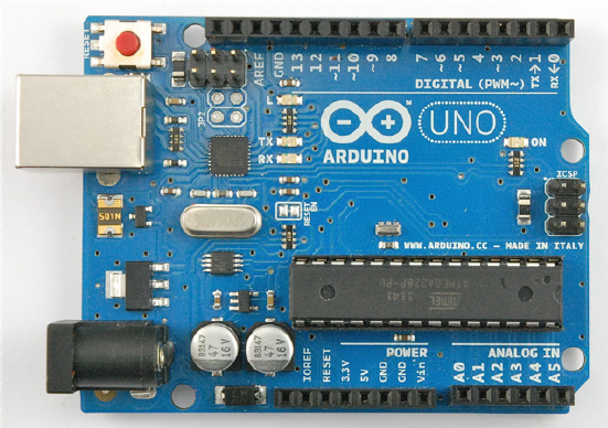 Arduino UNO
Led Blink
The Arduino has rows of connectors along both sides that are used to connect
to electronic devices and plug-in 'shields' that allow the Arduino to do
more.
However, the Arduino also has a single LED that you can control from
your sketches. This LED is built onto the Arduino board and is often referred
to as the 'L' LED as this is how it is labelled on the board.
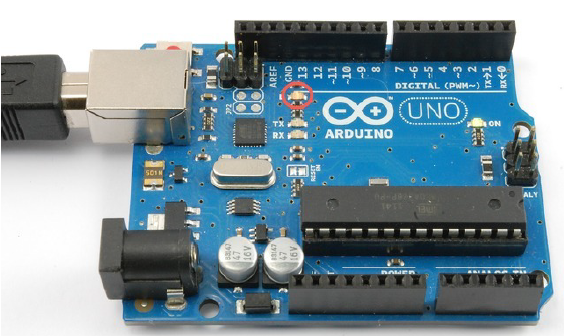 Arduino uno Led Placement
Loading the 'Blink' Example
We may find that your Arduino board's 'L' LED already blinks when you
connect it to a USB plug. This is because Arduino boards are generally
shipped with the 'Blink' sketch preinstalled.
In this we will reprogram the Arduino with our own Blink sketch and
then change the rate at which it blinks.Setup your Arduino IDE and made
sure that you could find the right serial port for it to connect to your
Arduino board. The time has now come to put that connection to the test
and program your Arduino board. Load the 'Blink' sketch that you will find
in the IDE's menu system under File→ Examples→ 01.Basics
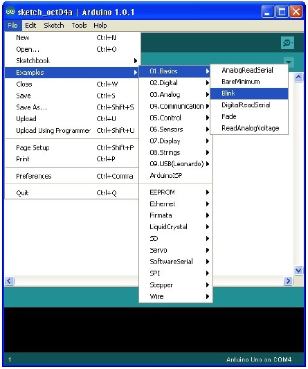 Arduino IDE
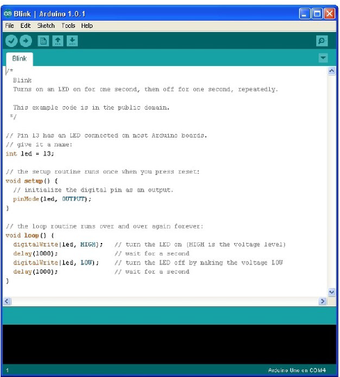
When the sketch window opens, enlarge it so that you can see the whole
of the sketch in the window.
Uploading Blink to the Board
Attach your Arduino board to your computer with the USB cable and check
that the 'Board Type' and 'Serial Port' are set correctly.
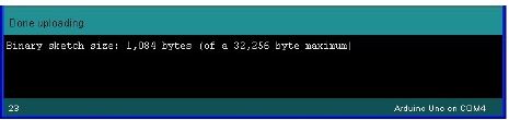
If you watch the status area of the IDE, you will see a progress bar and
a series of messages. At first it will say 'Compiling Sketch..'. This converts
the sketch into a format suitable for uploading to the board.
Next, the status will change to 'Uploading'. At this point, the LEDs on
the Arduino should start to flicker as the sketch is transferred.
Finally, the staus will change to 'Done'.
How 'Blink' Works
Here is the code for the Blink sketch.
/*
Blink
Turns on an LED on for one second, then off for one second, repeatedly.
This example code is in the public domain.
*/
// Pin 13 has an LED connected on most Arduino boards.
// give it a name:
int led = 13;
// the setup routine runs once when you press reset:
void setup() {
// initialize the digital pin as an output.
pinMode(led, OUTPUT);
}
// the loop routine runs over and over again forever:
void loop() {
digitalWrite(led, HIGH); // turn the LED on (HIGH is the voltage level)
delay(1000); // wait for a second
digitalWrite(led, LOW); // turn the LED off by making the voltage LOW
delay(1000); // wait for a second
}
The first thing to note is that quite a lot of this sketch is what is
called 'comments'. Comments are not actual program instructions, they are
just comments about how the program works. They are there for out benefit,
so that there is some explanation to accompany the sketch.
Everything between /* and */ at the top of the sketch is a block
comment, that explains what the sketch is for.
There are also single line comments that start with // and everything
up intil the end of the line counts as being a comment.
The first actual line of code is:
int led = 13;
As the comment above explains, this is giving a name to the pin that the LED is attached to.
This is 13 on most Arduinos, including the Uno.
Next, we have the 'setup' function. Again, as the comment says, this is run when the reset
button is pressed. It is also run whenever the board resets for any reason, such as power
first being applied to it, or after a sketch has been uploaded.
void setup() {
// initialize the digital pin as an output.
pinMode(led, OUTPUT);
}
Every Arduino sketch must have a 'setup' function, and the part of it where you might want to
add instructions of your own is between the { and the }.
In this case, there is just one command there, which, as the comment states tells the
Arduino board that we are going to use the LED pin as an output.
It is also mandatory for a sketch to have a 'loop' function. Unlike the 'setup' functio n
that o nly runs o nce, after a reset, the 'lo o p' function will, after it has finished
running its commands, immediately start again.
void loop() {
digitalWrite(led, HIGH); // turn the LED on (HIGH is the voltage level)
delay(1000); // wait for a second
digitalWrite(led, LOW); // turn the LED off by making the voltage LOW
delay(1000); // wait for a second
}
Inside the loop function, the commands first of all turn the LED pin on (HIGH), then 'delay' for
1000 milliseconds (1 second), then turn the LED pin off and pause for another second.
Button Interface
Pushbuttons or switches connect two points in a circuit when you press them. This example turns on the built-in LED on pin 13 when you press the button.
Hardware:
Arduino or Genuino Board
Momentary button or Switch
10K ohm resistor
Hook-up wires
Breadboard
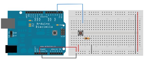 Circuit of Button
Connect three wires to the board. The first two, red and black, connect to the two long vertical rows on the side of the breadboard to provide access to the 5 volt supply and ground. The third wire goes from digital pin 2 to one leg of the pushbutton. That same leg of the button connects through a pull-down resistor (here 10K ohm) to ground. The other leg of the button connects to the 5 volt supply.
When the pushbutton is open (unpressed) there is no connection between the two legs of the pushbutton, so the pin is connected to ground (through the pull-down resistor) and we read a LOW. When the button is closed (pressed), it makes a connection between its two legs, connecting the pin to 5 volts, so that we read a HIGH.
You can also wire this circuit the opposite way, with a pullup resistor keeping the input HIGH, and going LOW when the button is pressed. If so, the behavior of the sketch will be reversed, with the LED normally on and turning off when you press the button.
If you disconnect the digital I/O pin from everything, the LED may blink erratically. This is because the input is "floating" - that is, it will randomly return either HIGH or LOW. That's why you need a pull-up or pull-down resistor in the circuit.
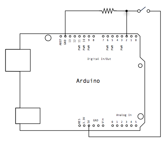 Schematic of Button
/*Button

 Turns on and off a light emitting diode(LED) connected to digital
 pin 13, when pressing a pushbutton attached to pin 2.


 The circuit:
 * LED attached from pin 13 to ground
 * pushbutton attached to pin 2 from +5V
 * 10K resistor attached to pin 2 from ground

 * Note: on most Arduinos there is already an LED on the board
 attached to pin 13.


 created 2005
 by DojoDave
 modified 30 Aug 2011
 by Tom Igoe

 This example code is in the public domain.

 http://www.arduino.cc/en/Tutorial/Button
 */

// constants won't change. They're used here to
// set pin numbers:
const int buttonPin = 2;     // the number of the pushbutton pin
const int ledPin =  13;      // the number of the LED pin

// variables will change:
int buttonState = 0;         // variable for reading the pushbutton status

void setup() {
  // initialize the LED pin as an output:
  pinMode(ledPin, OUTPUT);
  // initialize the pushbutton pin as an input:
  pinMode(buttonPin, INPUT);
}

void loop() {
  // read the state of the pushbutton value:
  buttonState = digitalRead(buttonPin);

  // check if the pushbutton is pressed.
  // if it is, the buttonState is HIGH:
  if (buttonState == HIGH) {
    // turn LED on:
    digitalWrite(ledPin, HIGH);
  } else {
    // turn LED off:
    digitalWrite(ledPin, LOW);
  }
}
Input Pullup:
Pushbuttons or switches connect two points in a circuit when you press them. When the pushbutton is open (unpressed) there is no connection between the two legs of the pushbutton. Because the internal pull-up on pin 2 is active and connected to 5V, we read HIGH when the button is open. When the button is closed, the Arduino reads LOW because a connection to ground is completed.
Now that your setup has been completed, move into the main loop of your code. When your button is not pressed, the internal pull-up resistor connects to 5 volts. This causes the Arduino to report "1" or HIGH. When the button is pressed, the Arduino pin is pulled to ground, causing the Arduino report a "0", or LOW.
void setup() {
  //configure pin2 as an input and enable the internal pull-up resistor
  pinMode(2, INPUT_PULLUP);
  pinMode(13, OUTPUT);

}

void loop() {
  //read the pushbutton value into a variable
  int sensorVal = digitalRead(2);

  // Keep in mind the pullup means the pushbutton's
  // logic is inverted. It goes HIGH when it's open,
  // and LOW when it's pressed. Turn on pin 13 when the
  // button's pressed, and off when it's not:
  if (sensorVal == HIGH) {
    digitalWrite(13, LOW);
  } else {
    digitalWrite(13, HIGH);
  }
}
Debounce:
Pushbuttons often generate spurious open/close transitions when pressed, due to mechanical and physical issues: these transitions may be read as multiple presses in a very short time fooling the program. This example demonstrates how to debounce an input, which means checking twice in a short period of time to make sure the pushbutton is definitely pressed. Without debouncing, pressing the button once may cause unpredictable results.
const int buttonPin = 2;    // the number of the pushbutton pin
const int ledPin = 13;      // the number of the LED pin

// Variables will change:
int ledState = HIGH;         // the current state of the output pin
int buttonState;             // the current reading from the input pin
int lastButtonState = LOW;   // the previous reading from the input pin

// the following variables are long's because the time, measured in miliseconds,
// will quickly become a bigger number than can be stored in an int.
long lastDebounceTime = 0;  // the last time the output pin was toggled
long debounceDelay = 50;    // the debounce time; increase if the output flickers

void setup() {
  pinMode(buttonPin, INPUT);
  pinMode(ledPin, OUTPUT);

  // set initial LED state
  digitalWrite(ledPin, ledState);
}

void loop() {
  // read the state of the switch into a local variable:
  int reading = digitalRead(buttonPin);

  // check to see if you just pressed the button
  // (i.e. the input went from LOW to HIGH),  and you've waited
  // long enough since the last press to ignore any noise:

  // If the switch changed, due to noise or pressing:
  if (reading != lastButtonState) {
    // reset the debouncing timer
    lastDebounceTime = millis();
  }

  if ((millis() - lastDebounceTime) > debounceDelay) {
    // whatever the reading is at, it's been there for longer
    // than the debounce delay, so take it as the actual current state:

    // if the button state has changed:
    if (reading != buttonState) {
      buttonState = reading;

      // only toggle the LED if the new button state is HIGH
      if (buttonState == HIGH) {
        ledState = !ledState;
      }
    }
  }

  // set the LED:
  digitalWrite(ledPin, ledState);

  // save the reading.  Next time through the loop,
  // it'll be the lastButtonState:
  lastButtonState = reading;
}
Analog to Digital Converter:
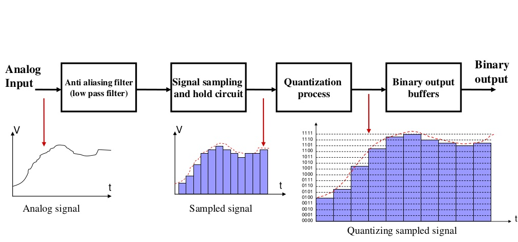
Analog to Digital converter Analog to digital converter is an IC responsible of converting analog signal continuous in amplitude and time to digital signals (binary numbers), but under certain conditions, for a PC or an ECU like a microcontroller or a PLC can understand in order to be processed and stored by these systems (the PC, ECU or PLC).
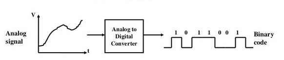 ADC Conversion
 ADC Conversion II
• Resolution: the number of different voltage levels (i.e.,
states) used to discretize an input signal.
• Resolution values range from 256 states (8 bits) to
4,294,967,296 states (32 bits).
• The Arduino uses 1024 states (10 bits).
• Smallest measurable voltage change is 5V/1024 or 4.8 mV.
• Maximum sample rate is 10,000 times a second.
Analog Input:
In this, we use a variable resistor (a potentiometer or a photoresistor), we read its value using one analog input of an Arduino or Genuino board and we change the blink rate of the built-in LED accordingly. The resistor's analog value is read as a voltage because this is how the analog inputs work.
Hardware Required
Arduino or Genuino Board
Potentiometer or
10K ohm photoresistor and 10K ohm resistor
built-in LED on pin 13 or
220 ohm resistor and red LED
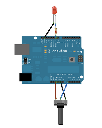
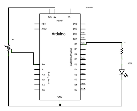
Circuit
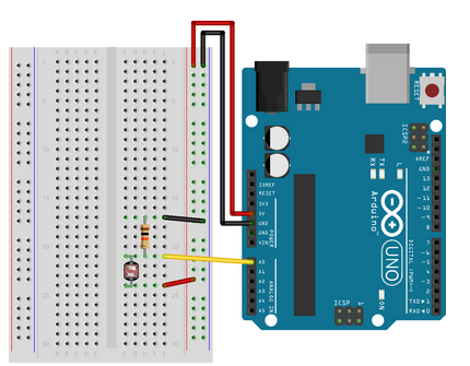 Breadboard Connection
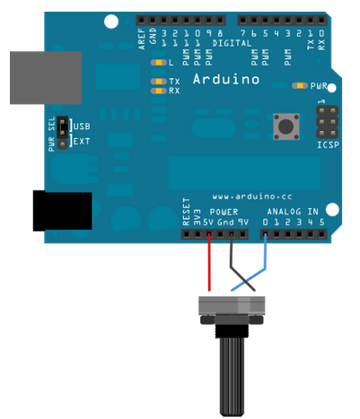 Potentiometer Connection
Connect three wires to the Arduino or Genuino board. The first goes to ground from one of the outer pins of the potentiometer. The second goes from 5 volts to the other outer pin of the potentiometer. The third goes from analog input 0 to the middle pin of the potentiometer.
For this example, it is possible to use the board's built in LED attached to pin 13. To use an additional LED, attach its longer leg (the positive leg, or anode), to digital pin 13 in series with the 220 ohm resistor, and it's shorter leg (the negative leg, or cathode) to the ground (GND) pin next to pin 13.
The circuit based on a photoresistor uses a resistor divider to allow the high impedence Analog input to measure the voltage. These inputs do not draw almost any current, therefore by Ohm's law the voltage measured on the other end of a resistor connected to 5V is always 5V, regardless the resistor's value. To get a voltage proportional to the photoresistor value, a resistor divider is necessary. This circuit uses a variable resistor, a fixed resistor and the measurement point is in the middle of the resistors. The voltage measured (Vout) follows this formula:
Vout=Vin*(R2/(R1+R2))
where Vin is 5V, R2 is 10k ohm and R1 is the photoresistor value that ranges from 1M ohm in darkness to 10k ohm in daylight (10 lumen) and less than 1k ohm in bright light or sunlight (>100 lumen).
Arduino with Photoresistor
int sensorPin = A0;    // select the input pin for the potentiometer
int ledPin = 13;      // select the pin for the LED
int sensorValue = 0;  // variable to store the value coming from the sensor

void setup() {
  // declare the ledPin as an OUTPUT:
  pinMode(ledPin, OUTPUT);
}

void loop() {
  // read the value from the sensor:
  sensorValue = analogRead(sensorPin);
  // turn the ledPin on
  digitalWrite(ledPin, HIGH);
  // stop the program for  milliseconds:
  delay(sensorValue);
  // turn the ledPin off:
  digitalWrite(ledPin, LOW);
  // stop the program for for  milliseconds:
  delay(sensorValue);
}
At the beginning of this sketch, the variable sensorPin is set to to analog pin 0, where your potentiometer is attached, and ledPin is set to digital pin 13. You'll also create another variable, sensorValue to store the values read from your sensor.
The analogRead() command converts the input voltage range, 0 to 5 volts, to a digital value between 0 and 1023. This is done by a circuit inside the microcontroller called an analog-to-digital converter or ADC.
By turning the shaft of the potentiometer, you change the amount of resistance on either side of the center pin (or wiper) of the potentiometer. This changes the relative resistances between the center pin and the two outside pins, giving you a different voltage at the analog input. When the shaft is turned all the way in one direction, there is no resistance between the center pin and the pin connected to ground. The voltage at the center pin then is 0 volts, and analogRead() returns 0.
When the shaft is turned all the way in the other direction, there is no resistance between the center pin and the pin connected to +5 volts. The voltage at the center pin then is 5 volts, and analogRead() returns 1023. In between, analogRead() returns a number between 0 and 1023 that is proportional to the amount of voltage being applied to the pin.
That value, stored in sensorValue, is used to set a delay() for your blink cycle. The higher the value, the longer the cycle, the smaller the value, the shorter the cycle. The value is read at the beginning of the cycle, therefore the on/off time is always equal.
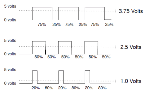
Arduino PWM:
This example shows you how to read an analog input pin, map the result to a range from 0 to 255, use that result to set the pulse width modulation (PWM) of an output pin to dim or brighten an LED and print the values on the serial monitor of the Arduino Software (IDE).
PWM(Pulse Width Modulation)
PMW Pins
Command:   analogWrite(pin,value) //value is duty cycle: between 0 and 255

//Examples:
   analogWrite(9, 128)
   for a 50% duty cycle

   analogWrite(11, 64)
   for a 25% duty cycle
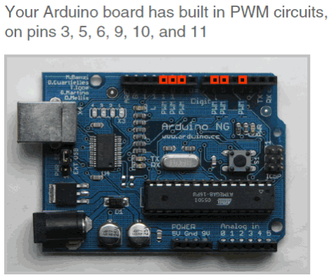 Arduino PWM pins
PWM Duty Cycle
Output voltage = (on_time / cycle_time) * 5V
 PWM Duty Cycle
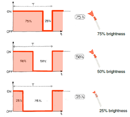 Led Brightness Control
Arduino Serial Communication
-It is called "Serial” because data is broken down into bits, each sent one after the other down a single wire.
-Toggle a pin to send data, just like blinking an LED • You could implement sending serial data with digitalWrite( ) and delay( )
-A single data wire needed to send data. One other to receive.
-The single ASCII character ‘B’ is sent as:
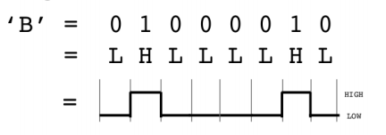
-Compiling turns your program into binary data (ones and zeros)
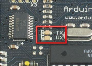
-Uploading sends the bits through USB cable to the Arduino
-The two LEDs near the USB connector blink when data is
transmitted
-RX blinks when the Arduino is
receiving data
-TX blinks when the Arduino is
transmitting data
Some Commands
• Serial.begin()
- e.g., Serial.begin(9600)
• Serial.print() or Serial.println()
- e.g., Serial.print(value)
• Serial.read()
• Serial.available()
• Serial.write()
• Serial.parseInt()
Analog In, Out Serial
This shows you how to read an analog input pin, map the result to a range from 0 to 255, use that result to set the pulse width modulation (PWM) of an output pin to dim or brighten an LED and print the values on the serial monitor of the Arduino Software (IDE).
Connect one pin from your pot to 5V, the center pin to analog pin 0 and the remaining pin to ground. Next, connect a 220 ohm current limiting resistor to digital pin 9, with an LED in series. The long, positive leg (the anode) of the LED should be connected to the output from the resistor, with the shorter, negative leg (the cathode) connected to ground.
In the sketch below, after declaring two pin assignments (analog 0 for our potentiometer and digital 9 for your LED) and two variables, sensorValue and outputValue, the only things that you do in the setup() function is to begin serial communication.
Next, in the main loop, sensorValue is assigned to store the raw analog value read from the potentiometer. Arduino has an analogRead range from 0 to 1023, and an analogWrite range only from 0 to 255, therefore the data from the potentiometer needs to be converted to fit into the smaller range before using it to dim the LED.
In order to convert this value, use a function called map():
outputValue = map(sensorValue, 0, 1023, 0, 255);
outputValue is assigned to equal the scaled value from the potentiometer. map() accepts five arguments: The value to be mapped, the low range and high values of the input data, and the low and high values for that data to be remapped to. In this case, the sensor data is mapped down from its original range of 0 to 1023 to 0 to 255.
The newly mapped sensor data is then output to the analogOutPin dimming or brightening the LED as the potentiometer is turned. Finally, both the raw and scaled sensor values are sent to the Arduino Software (IDE) serial monitor window, in a steady stream of data.
const int analogInPin = A0;  // Analog input pin that the potentiometer is attached to
const int analogOutPin = 9; // Analog output pin that the LED is attached to

int sensorValue = 0;        // value read from the pot
int outputValue = 0;        // value output to the PWM (analog out)

void setup() {
  // initialize serial communications at 9600 bps:
  Serial.begin(9600);
}

void loop() {
  // read the analog in value:
  sensorValue = analogRead(analogInPin);
  // map it to the range of the analog out:
  outputValue = map(sensorValue, 0, 1023, 0, 255);
  // change the analog out value:
  analogWrite(analogOutPin, outputValue);

  // print the results to the serial monitor:
  Serial.print("sensor = ");
  Serial.print(sensorValue);
  Serial.print("\t output = ");
  Serial.println(outputValue);

  // wait 2 milliseconds before the next loop
  // for the analog-to-digital converter to settle
  // after the last reading:
  delay(2);
}
Bluetooth tutorial:
Bluetooth is a very popular mode of communication. Due to its availability, low cost and ease of use, Bluetooth finds its application in a large no. of fields. It is also a favorite choice in embedded systems.
Latest Bluetooth modules are based on BLE (Bluetooth Low Energy) subset of Bluetooth 4.0.However, these are still a little costly and not widely developed yet.
Two popular and commonly available Bluetooth modules are: – HC-05 & HC-06.There is no much difference between them in terms of cost but HC-05 is used most of time. The reason is HC-05 can act as both master and slave whereas HC-06 can act only as slave.
Now, what is master and slave mode? For a simplistic definition, a master is someone who initiates (send request) connection with a slave. Ex. When you connect your smartphone with Bluetooth module, smartphone act as master and send request to slave Bluetooth module.HC-05 is by default in slave mode. Also a master can connect up-to 7 slave as defined in IEEE 802.15 protocol but vice-versa is not possible.
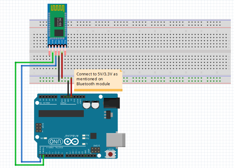
Bluetooth communicates in Serial mode i.e. Rx,Tx. Bluetooth module has generally 4 pins-Vcc,Gnd,Rx,Tx.
Rx of Bluetooth connects with Tx of Arduino and similarly Tx with Rx of Arduino.
For Software part, first we have define baud rate of Serial communication-
Serial.begin(9600);
Most of the apps use characters to send information. Therefore, we define a global char variable to store incoming byte.
char incomingByte;
Before storing the incoming character, first we check if there is any data available in serial to avoid processor time wastage. If there is data available, we store it in variable incomingByte. Then we can compare it and perform actions according to our needs.
Demo Code
If(Serial.available>0)
{
incomingByte = Serial.read();
If(incomingByte==’a’)
{
If(digitalRead(led))
digitalWrite(led,LOW);
else
digitalWrite(led,HIGH);
}
}
Hence,the complete code is –
int led = 13;

char incomingByte; // variable to receive data from the serial port

void setup()
{
Serial.begin(9600);      //define baud rate
pinMode(led, OUTPUT);
}


void loop()
{
  if( Serial.available() > 0 ) // if data is available to read
{
incomingByte = Serial.read();  //store incoming data in incomingByte
if(incomingByte == 'a')
{        //if comparison is true
if(digitalRead(led))
digitalWrite(led,LOW);    //if led is ON,turn it OFF
else
digitalWrite(led,HIGH);    //if led is OFF,turn it ON
}
}
}
Circuit diagram-
Problem's Faced And Solution
If you use the above configuration, you might experience some problems like you can’t upload your code while Bluetooth module is connected with Arduino and smartphone fails to pair with Bluetooth module several times. The main reason for this is first Serial port or Serial of Arduino board is also connected with usb port. Thus Arduino may be in serial communication with both your Bluetooth module and computer through usb cable.
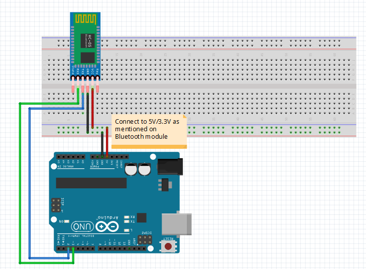
A simple and easy solution for this is to use different serial port for Bluetooth communication. This is not a problem for some Arduino boards like Arduino Mega which has 4 hardware serial ports but for boards like Arduino Uno which have only one hardware serial port, this is quite troublesome.
Luckily, we can solve this through software. We take any two digital pins as Rx,Tx and use it as Serial port through software.However,we have a limit of how much we can use it.These Software Serial ports can’t match up-to the speeds of hardware serial ports.
We define these software serial ports through SoftwareSerial library of Arduino. This library came bundled with Arduino IDE but we have to tell the IDE that we are using this library.
#include<SoftwareSerial.h>
Next, we choose 2 digital pins (let’s use 2, 3 for example) for Tx, Rx and define our new software serial port with name, let’s say-BTSerial
SoftwareSerial BTSerial(2,3);
This time lets print what is coming through Bluetooth to Serial monitor of Arduino. Thus, we are using both hardware serial and software serial this time.
BTSerial.begin(9600);
Serial.begin(9600);
As we done above, we check if the date is available. If available, we store it in incomingByte. This time we do an extra step of printing this variable to the Serial monitor.
Demo Code
If(BTSerial.available>0)
{
incomingByte = BTSerial.read();
Serial.println(incomingByte);
If(incomingByte==’a’)
{
If(digitalRead(led))
digitalWrite(led,LOW);
else
digitalWrite(led,HIGH);
}
}
This way we can send data to Bluetooth and see it on Serial monitor. It very useful while writing comparison logic during debugging.
Hence,the complete code is –
#include   //including library

int led = 13;

char incomingByte; // variable to receive data from the serial port

const int rxpin = 2;    //connect bluetooth tx pin here
const int txpin = 3;    //connect bluetooth rx pin here

SoftwareSerial BTSerial(rxpin, txpin);

char variable = 'a';     //variable to be compared

void setup()
{
BTSerial.begin(9600); // start bluetooth serial communication at 9600bps
Serial.begin(9600);
pinMode(led, OUTPUT);
}


void loop()
{
  if( BTSerial.available() > 0 ) // if data is available to read
{
incomingByte = BTSerial.read();  //store it in incomingByte variable
Serial.println(incomingByte);    //print it to Serial monitor
if(incomingByte == variable)
{        //if comparison is true
if(digitalRead(led))
digitalWrite(led,LOW);    //if led is ON
else
digitalWrite(led,HIGH);    //if led is OFF
}
}
}
Circuit diagram-
This code should be used when you are communicating with a smartphone and Bluetooth module. If you want to use Bluetooth modules at both ends, one Bluetooth module should be configured as master through AT commands.You can find the guides from following links-
https://alselectro.wordpress.com/2014/10/21/bluetooth-hc05-how-to-pair-two-modules/
http://www.instructables.com/id/AT-command-mode-of-HC-05-Bluetooth-module/
Comments:
If You Like this tutorial series, Please Like our Page