Instructables link to this Project is Here
Self-Balancing RobotAfter getting so much frustrated over PID tuning of quadcopter, I decided
to master PID first on some basic project. Self-balancing robot seems an
idle choice. Since it’s not new and still challenging, I decided to go
for it.
I never thought it will be easy and I am not disappointed. I learned
a lot from it and decided to share it with others.
Concept/Theory
What is Self-balancing robot?
Self-Balance Robot is somewhat which balances itself and automatically corrects its position on disturbance.
How it works?
It will be prevented from falling by giving acceleration to the wheels according to its inclination from the vertical. If the bot gets tilts by an angle, than in the frame of the wheels, the center of mass of the bot will experience a pseudo force which will apply a torque opposite to the direction of tilt.
That’s the technical answer. If you want to know in simple terms, recall the stick balancing game which you used to play in your childhood.Yeah, the one in which you balance stick in your hand. If stick falls forward, you move your hand forward and vice-versa. Now consider the stick your robot and the 2 tire’s as your hands. The same technique you used to balance stick will now be used to balance robot.
lIf the bot gets tilts by an angle, than in the frame of the wheels, the centre of mass of the bot will experience a pseudo force which will apply a torque opposite to the direction of tilt.
Materials
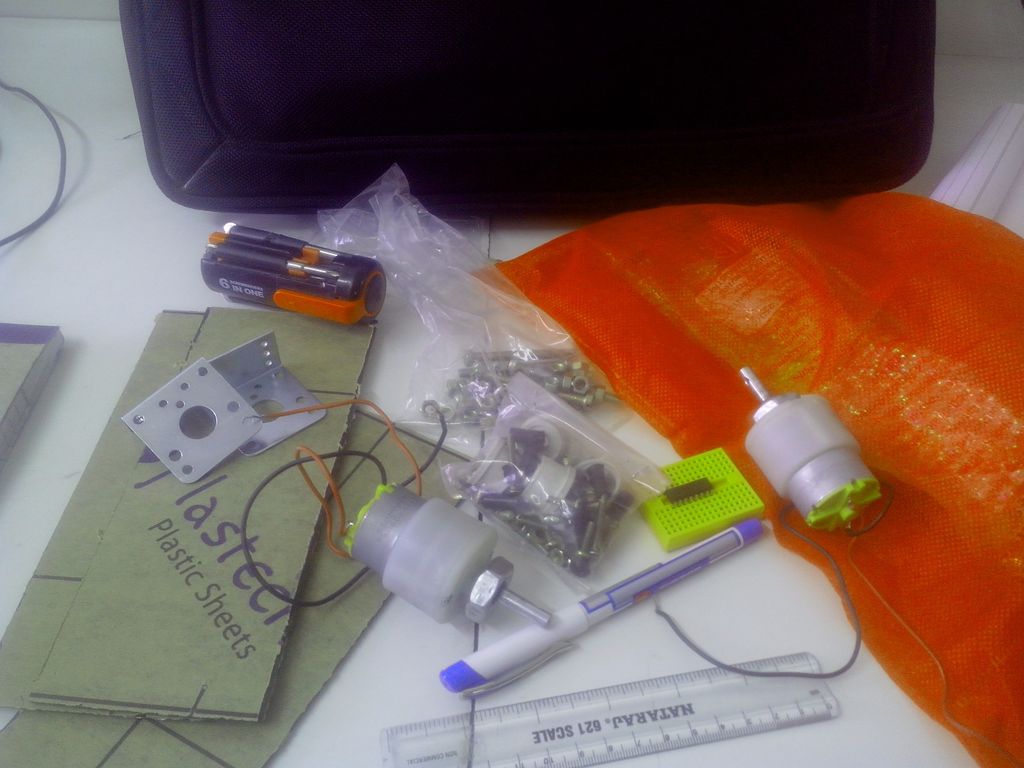
First we need some materials to build our chassis. I choose Acrylic sheet.
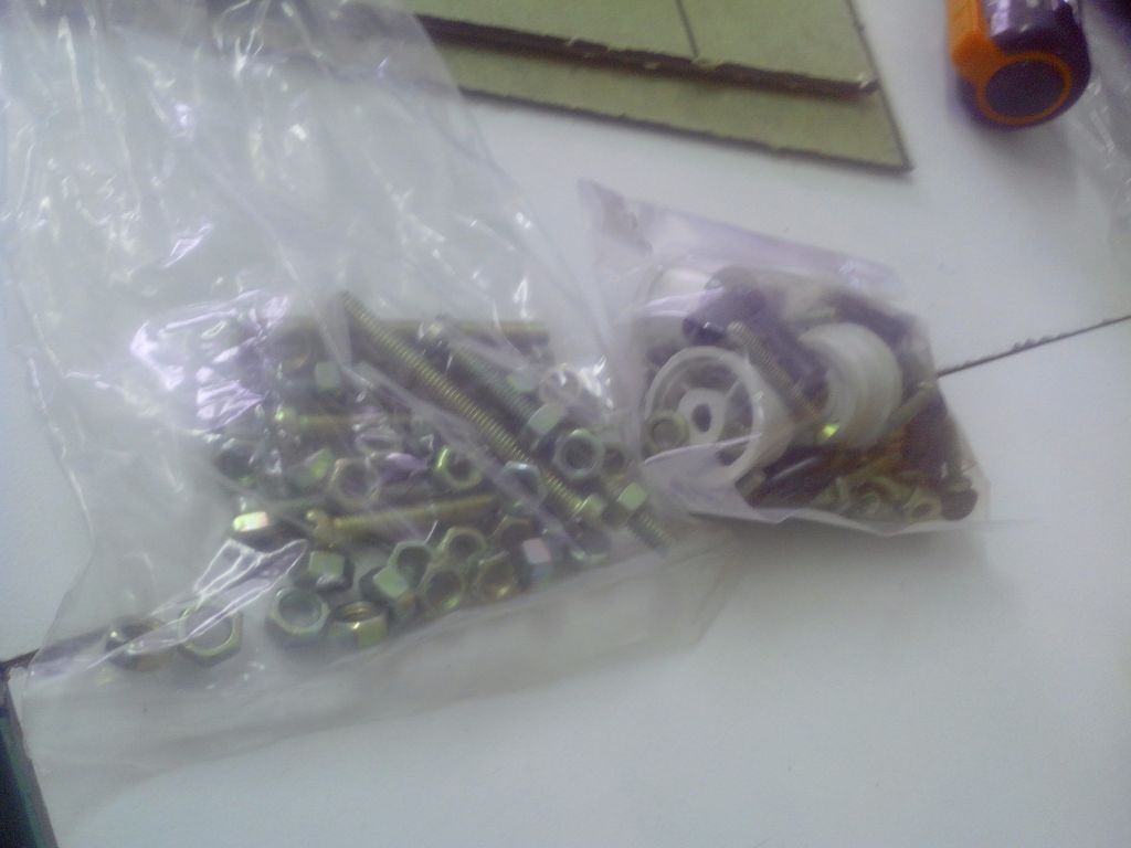
Some screws will be needed according to design which we will discuss shortly
plus 2 tires.
For remaining Electronics part, here’s the list
a) 1x Arduino UNO
b) 1x HC-05 Bluetooth Module
c) 1x MPU 6050
d) 1x L293D
e) 1x IC7805
f) 1x Battery
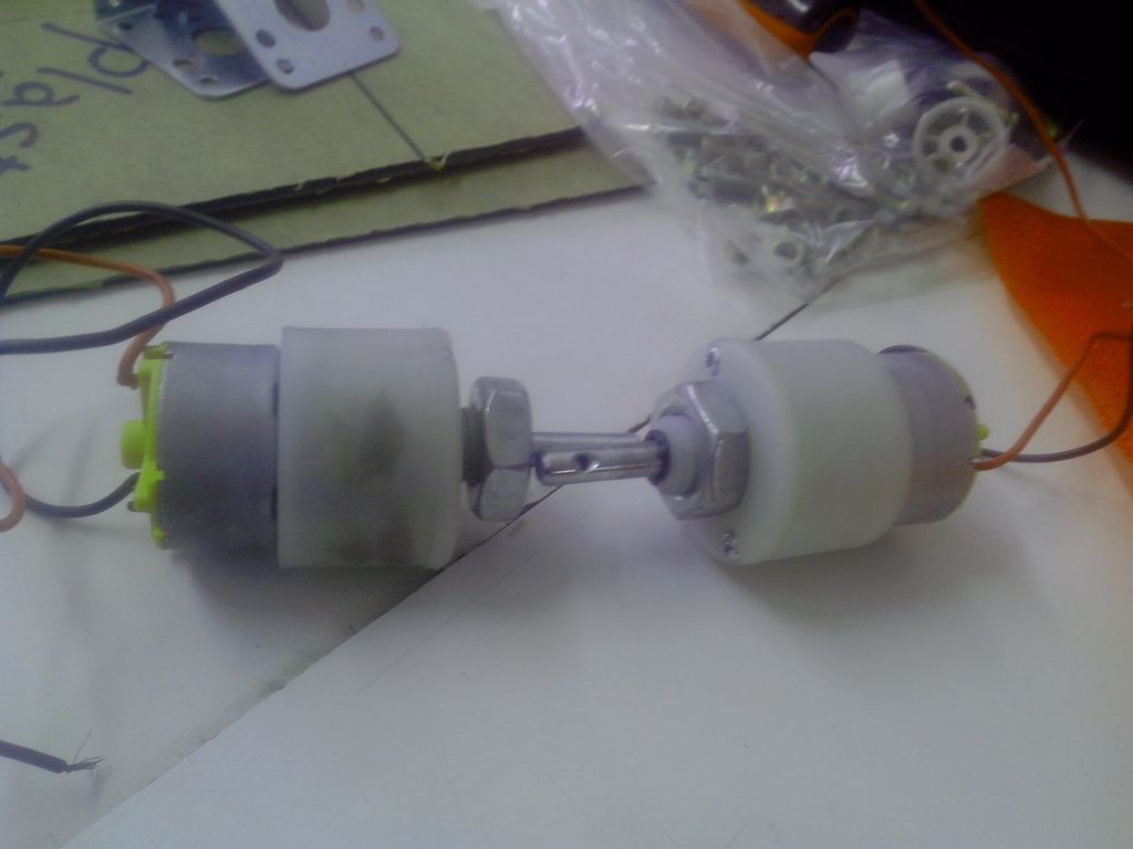
g) 2x 500 rpm MotorsAcrylic Sheet for building chassis
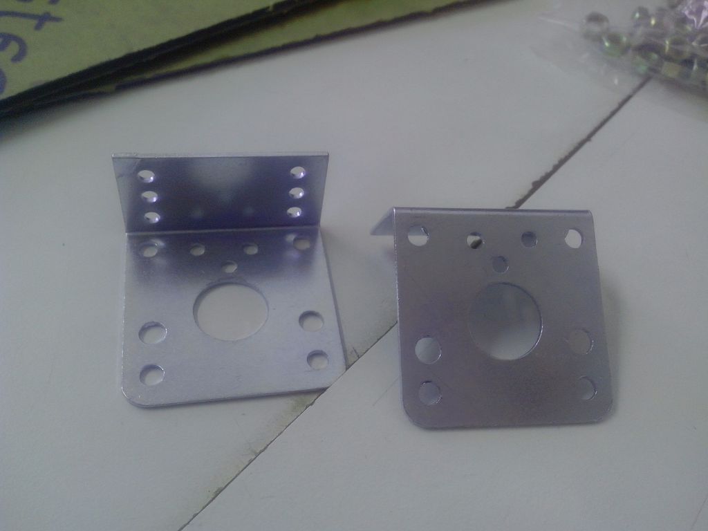
h) 2x Motor clamps with screws
i) Some Large Screws
j) Jumper wires
We will talk about the choices of these components later
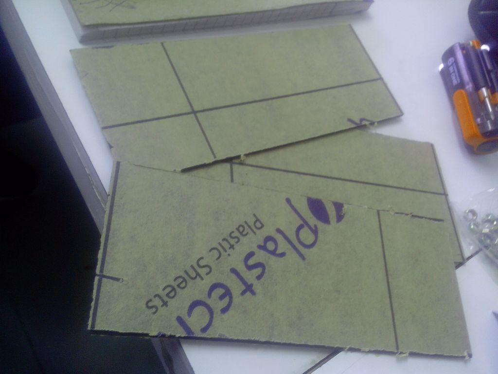
Chassis
I designed my chassis using acrylic sheet (just to save trouble of drilling
holes). However, it can be designed using Wooden plank, plastic sheet etc.
too. In my opinion, wooden plank will be good choice if you want to build
a stable chassis and plan to mount something on it. Anyways, I cut sheet
to form 3 levels/floors. It’s not mandatory, but is a good practice.
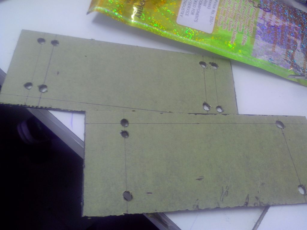
No. of levels can be increased if desired. After markings, holes
has to be made for screws. For making holes, I simply use Solder iron.
(Here acrylic sheet comes to rescue. After making holes, I realized that
I made mistakes which I corrected easily) If you are using, wood, double
check your markings.
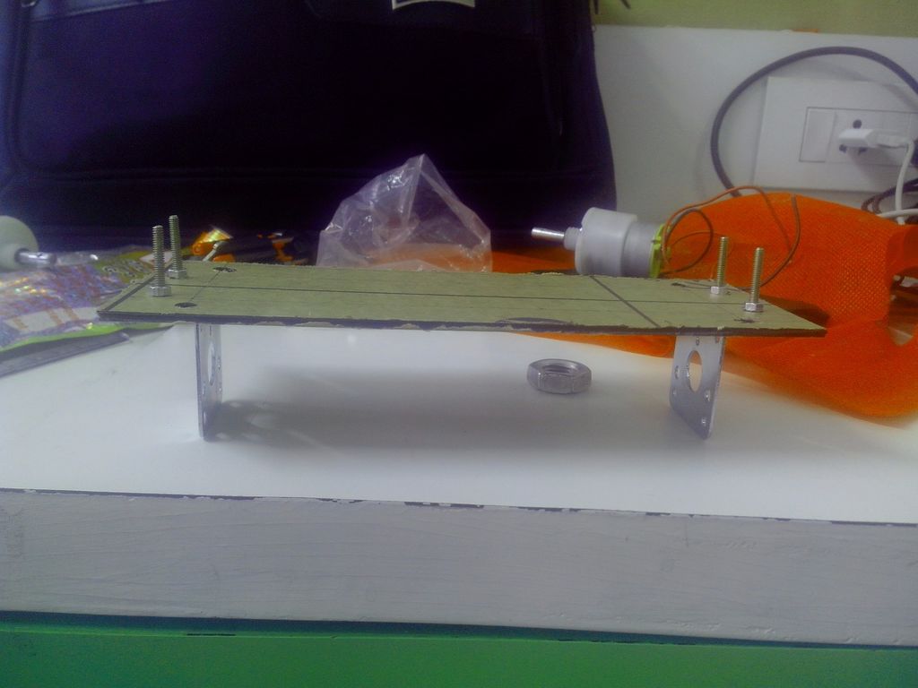
Choice of tires should be ones with good grip (rubber, if available)
and large surface area.
Assemble the whole chassis and we are ready to move to electronics
part.
Connections
A Fritzing file is shown below showing all connections.
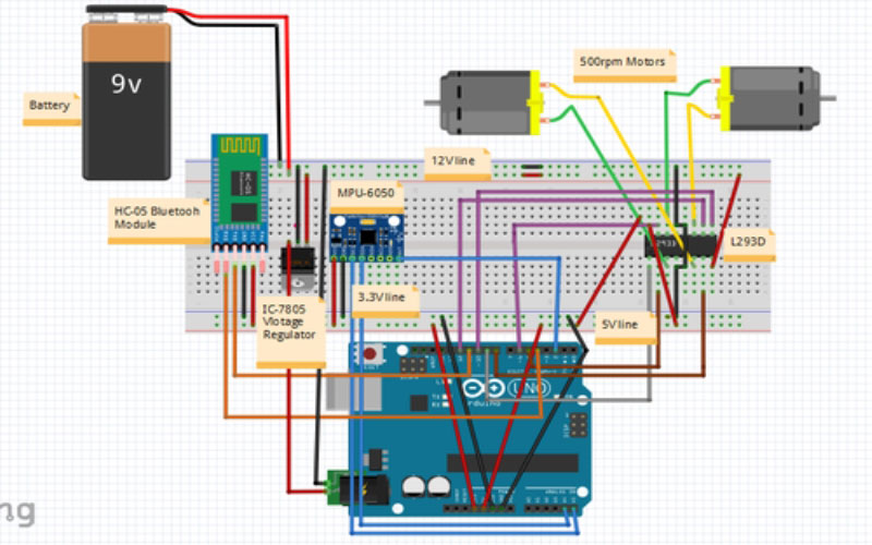 Fritzing Circuit
MPU-6050 is used due to its DMP capability.It can procees the Raw Accelerometer
& Gyro values to give the Yaw,Pitch,Roll.It greatly decreases the computation
overhead.
HC-05 bluetooth module is used for communication between Bot and
Android app.
L293d motor driver is used for controlling motor.
IC7805 voltage Regulator is used for providing 5V power supply to Arduino.
However,using this IC is not necessary and battery can be directly plugged
to Arduino.This is just used for Safety Purposes.
Now as everything set, we can dive into the code for our robot.
Software
Arduino is known for its friendly coding environment and large open source
user libraries which makes the prototyping really easy.
I first started with separate Accelerometer and Gyroscope. But as
things progressed, I find it difficult to balance with computational overhead
of calculating pitch & roll (using kalman/Complementary filter).When
I switched to MPU-6050, it drastically improved the balancing.
To use the DMP of MPU, I used
Jeff Rowberg’s
I2CDevlibraries. To calibrate the mpu, I used
Luis Rodenas’s
sketch.
Now, we can determine the angle of bot with vertical. But how can
we calculate the amount of force needed to push bot back to vertical when
it is unbalanced by some uncertain degrees from vertical. This is where
PID kicks in .PID will specify this force which will change according to
time and angle by which bot is unbalanced.
I will not go into technical details.
Brett Beauregard wrote a nice
PID library with explanation if you want.
To further speed up the motor response, I used
digitalIOPerformance library for fast writing of pins.
Finally for storing PID values in EEPROM of Arduino,
EEPROMex library for efficiency and clean code.
Complete code can be found on the
GITHUB.
PID Tuning
Frankly, this is the most difficult part of the process and also the most
crucial. You will spend many days working on it and yelling “WTH am I supposed
to do?” How much frustrating it may be but there is no escaping it? Control
engineers set the PID parameters by experience. It’s an art learnt through
experience.
There are various methods out there for PID tuning.
The best simple & easy method for PID tuning is-
-Set I and D term to 0, and adjust P so that the robot starts to oscillate
(move back and forth) about the balance position. P should be large enough
for the robot to move but not too large otherwise the movement would not
be smooth.
-With P set, increase I so that the robot accelerates faster when off
balance. With P and I properly tuned, the robot should be able to self-balance
for at least a few seconds.
-Finally, increase D so that the robot would move about its balanced position
more gentle, and there shouldn’t be any significant overshoots.
-If first attempt doesn’t give the satisfying results, reset PID values
and start over again with different value of P.
-Repeat the steps until you find a certain PID value which gives the satisfactory
results.
-A fine tuning can be done to further increase the performance of PID
system.
-In fine tuning, PID values are restricted to neighboring values and effects
are observed in practical situations.
Important Points
-There is no clear boundary for taking P, I or D values and is mostly
taken based on experience.
-Theoretically, ID values depends on the state of the system.Ex. Mechanical
Structure, Physical properties, Electrical properties (if any) etc.
-But practically, it also depends on the external conditions .Ex. Atmospheric
conditions etc.
-PID values and method of choosing PID values depends largely on the characteristics
of system. A method producing good result for a system may not work at
all for another system with different characteristics.
What P, I & D values means practically?
In case of Self-Balancing Robot-
-P-P determines the force with which the robot will correct itself. A
lower P shows robot’s inability to balance itself and a higher P will shows
the violent behavior.
-I-I determines the response time of robot for correcting itself. Higher the
P, Faster it will response.
-D- D determines the sensitivity of robot to the error in its state. It
is used to smoothen/depress the robot oscillations. A lower D is unable
to remove oscillations and a higher D will cause violent vibrations.
Depending on your PID tuning, the bot will be able balance itself
now.
APP
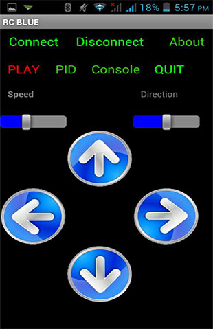
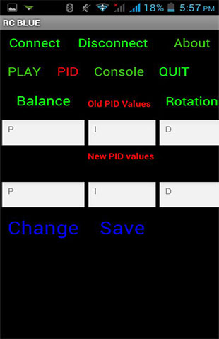
Re-uploading code every time to change PID values is very tiresome. So
I decided to attach Bluetooth and change values from my Android phone.
I saw many people using MIT App Inventor for building apps for such purposes.
I never used it before. So I thought, I must give it a shot. After watching
some tutorials and some apps from other people regarding Bluetooth connection,
I was all set. I must admit,App inventor revolutionize the app creation
by letting you make apps in a way even non-programmers can make it without
concerning what is happening behind the scenes.
MIT app inventor was fun except I have to deal large graphical blocks
even for simpler tasks. Arrangements of these blocks was tiresome and reading
it was pain.
You can find my app and Sample code from
here.
Note-Although Multi-scene was introduced in App inventor 2, it
treats every scene as separate app.For ex-you started some Bluetooth activity
in scene1 and paired a device and then switched to scene2.scene2 will be
completely unaware of the the pairing and tries to pair (& obviously
fails) a device. A good way of handling it is build a single scene app
and hide/show elements just like single page websites.
Congratulation!!!On your first self-balancing robot. Maybe you can
name it now, I called mine Chappie.
What’s next?
Well, now you have a self-balancing robot which you can control by Bluetooth.
Maybe you can upgrade it to Wi-Fi or use it as replacement to your 4 wheel
robot.
You can upgrade the Arduino to Raspberry pi to harness the power of mini-computer
e.g. Image processing etc.
You can also use decoder motor or stepper motors.it will also significantly
increases the performance. However, you will need to update the code accordingly.